MIXING & EFFECTS
Maximus Controls & Options
NOTE: Click on the screenshot above to jump to the help for the selected control section.
Overview
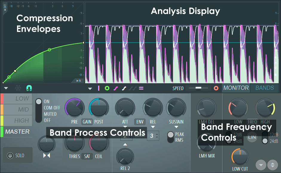
Maximus takes the input signal, passes it through a variable high-pass filter and then splits the signal into three user-defined frequency bands. Each frequency band can be treated independently with either saturation, compression, limiting or band level (EQ). The bands are then recombined and sent to the Master compressor. The controls for Maximus are explained in detail below.
Compression Envelopes
There are 4 independent compression envelopes in Maximus, one for each of the three user-definable frequency bands and one for the Master band. It is important to note that the compression envelope interacts closely with the PRE & POST GAIN, ATT & REL controls.
Compression Envelopes Controls
If you are familiar with regular compressors you will notice that Maximus does not have a threshold level control. More flexibly, the compression threshold and curve are set by a user-definable envelope (see below). There are 4 independent envelopes, three are assigned to frequency bands - Low, Mid, and High, and one to a Master envelope on the final output of the plugin. Input levels are represented by the horizontal axis and output levels by the vertical axis.
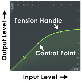
In the example (above) the point at which the compression curve deviates from the 1:1 input/output line (45 degree line), is the point where compression starts (in this case approximately -3 dB). This is also an example of a 'Soft Knee' curve to a maximum output level of +3 dB. NOTE: When the time variables (ATT, REL & SUSTAIN) are set to values shorter than frequencies of the waveform, the Compression Envelope behaves as a Waveshaper. When they are set longer than frequencies in the waveform, volume envelope compression is achieved.
- Move control points - Left-click the control point and drag to the desired position (the point will snap to the background grid unless SNAP is off, see below). Hold SHIFT while dragging to lock the vertical position, or Ctrl to lock the horizontal position.
- Change envelope curve - Left-click the desired tension handle and move up/down. Holding the Ctrl key will allow fine adjustment (tension handles automatically appear between control points). Right-click to reset curve tension.
- Change curve type - There are 5 curve types available to join control points, to select from a menu, Right-click a control point:
- Single Curve - Default mode for creating linear, or ease-in and ease-out curves (depending on the tension).
- Double Curve - Smooth 'S' curves.
- Hold - Single steps between points, handy for creating abrupt value changes in the envelope.
- Stairs - Multiple steps between the control points. Left-click on the tension handle and move your mouse up/down to change the step frequency.
- Smooth stairs - Multiple smooth steps between the control points. Left-click on the tension handle and move your mouse up/down to change the step frequency.
- Add control points - Right-click at the point where you want a new control point to appear.
- Delete control points - Right-click the point to be deleted and select 'Delete' from menu. Alternatively, hold ALT and Left-click.
Compression Envelope Options
Located along the bottom of the graph window, from left to right, are:
 Compression Mapping Envelope Options Menu -
- Open state file / Save state file - Opens/saves envelope states. Several different pre-defined state files are available.
- Copy state / Paste state - Use this to copy and paste envelopes, usually between instances of the EQ editor across open Edison's.
- Undo - Undoes the last envelope edit.
- Undo history / Last reset - Shows the editing history since the last reset.
- Flip vertically - Inverts the current envelope.
- Scale levels - Opens the Scale Level tool.
- Normalize levels - Scales the envelope so the highest and/or lowest levels reach +/- 100%.
- Decimate points - Opens a simple tool that allows manipulation of the number of control points in the envelope (useful in conjunction with Analyze audio file).
- Filter - Opens the Envelope Filter tool (useful in conjunction with Analyze audio file).
- Smooth up - Opens the Smooth Up tool that allows smoothing of the envelope shape (useful in conjunction with Analyze audio file).
- Smooth up abrupt changes - Quick removal of 'spikey' or sudden changes in the envelope.
- Turn all points smooth - Preset filter to quickly filter the envelope.
- Create sequence - Opens the Envelope Sequencer tool.
- Analyze audio file - Open, analyze and replicate the volume envelope of an input sound file. Drag and drop audio files directly on the Envelope editor for automatic analysis.
- FREEZE - Freezes envelope editing so that changes can't be made.
- SNAP - Snaps the envelope points to a grid.
General Options
Options Menu - Contains some general options for Maximus:
- Lock spare state - Prevents the alternate (spare) patch settings from being overwritten. This option is particularly useful when changing patches, since saved patches have their own spare state. For example, send your settings to the spare state (down-arrow button at the bottom right of the interface). Lock the spare state and switch to other presets. The spare state will contain your settings, rather than being stored in presets.
- Oversample - Oversampling is applied to the internal processing to achieve the highest audio quality. The compressor stages will also now respond to inter-sample peaks. NOTE: Oversampling consumes more CPU power and is most likely to benefit solo instruments that are exposed in the mix. It is less likely to benefit complex or dense mixes.
- Master Mid mode - Uses the MID frequency band to drive the MASTER compression envelope. The LOW and HIGH compression envelopes are OFF. This is useful for internal EQ sidechain type compression. Use the MID band to select the frequencies that control the MASTER (all bands) compression. For example, isolate the kick frequencies with the MID band, and cause those to pump all frequencies. It can also be used for Gating and De-Essing control, see the Tutorial section.
- Linear-phase filters (legacy mode) - Alternative Linear-phase band-split filters. The default filters are IIR. The linear-phase filters preserve the phase relationships in the signal, but come at the cost of greater CPU usage and approximately 2 ms more plugin delay, relative to the IIR filters. The band-split filter type you choose is entirely dependent on the material being processed and what sounds most pleasing to your ear.
- 0.2 dB compressor safety - Adds -0.2 dB of extra headroom to the compressior section to help avoid over 0 dB peaks.
- Histogram Enabled - Show a frequency histogram display on the background. In this display the line (creating a series of peaks), represents the level of frequencies from 20 Hz to 20 kHz.
- Range - Lowest dB activity metered. Choose from -60, -90 or -120 dB.
- Pivot slope - Choose slopes of 1.5, 3, 4.5 and 6 dB/octave. These slopes pivot the spectrum around 1 kHz, visually increasing the height of high frequency peaks and reducing the height of low frequency peaks. A setting of 4.5 dB/oct shows a spectrum that is closer to how you hear it. All frequencies sounding at a similar loudness will look flat. This can be useful for looking at the frequencies of your final mix. Use 1.5, 3 dB settings if you find you are aiming for a mix with less bass and more highs. A setting of 6 dB/oct shows the frequencies of a basic saw oscillator as flat. This may be useful during sound design. When set to 0 dB 'white noise' will look flat.
- Frequency precision - The number of bands used in the frequency spectrum. Higher settings come at the expense of visual display latency (although plugin audio latency remains unaffected).
- Time smoothing - Depending on the Average mode setting, Time smoothing has different effects on peak reactivity and persistence.
- Average mode OFF: The spectrum reacts to peaks. Smoothing sets how slowly the frequency peaks fall over time.
- Average mode ON: The spectrum shows the average of peaks over time. Smoothing sets how long the averaging time window is.
- Average mode (RMS) - Shows the average peak level rather than the instantaneous peak level.
- Heatmap Enabled - Shows the intensify of frequencies from 20 Hz to 20 kHz as changes in the intensity of vertical line. You can think of this as the 'top-down' view of the Frequency Histogram view (above).
- High precision - Shows more precise vertical lines. Switch this off to use an alternative algorithm that tends to blur the lowest frequency bands, but has the advantage it can be easier to identify the center frequency of these low frequency bands.
- Enhanced frequency - Thinner lines are used to represent frequency.
- Heatmap position - When the Heatmap is used together with the Frequency Histogram view, the Heatmap can be displayed above (Top) below (Bottom) or over (Full) the Histogram.
- About - Shows plugin credits and software information.
Analysis Display
There are two display modes accessed by selecting the BANDS or MONITOR tabs to the lower right of the display area. When the BAND cutoff or level values are adjusted while the display is in MONITOR mode it will momentarily snap to BANDS mode while the adjustment is made.
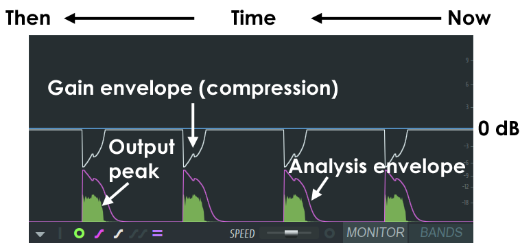
The MONITOR display is a valuable analysis tool to observe how the various compression and envelope settings are interacting with the input / output sounds. The example above shows a kick drum being ana lysed with a long release setting on the compression envelope. NOTES: Many of the display options work in combination with the selected frequency band and only show data for that band. Clicking on the display area will Pause the display.
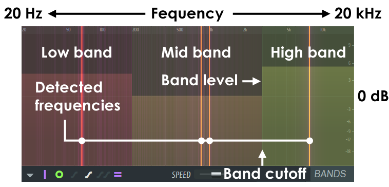
The BANDS display shows the LOW, MID and HIGH frequency bands. It is possible to adjust the band cutoff and band level by clicking on the boundaries between bands and dragging with the mouse. The band cut-offs are used to feed the LOW, MID and HIGH compression envelopes. The Output Spectrum display option is useful to determine what part of the frequency spectrum the input sounds occupy so that band cutoffs may be most accurately set.
Display Controls & Options
 Show main input peaks - Display the main input level graph.
 Show band input peaks - Displays the input level graphs for
the Low, Mid and High frequency bands, depending on the band selected.
Show band input peaks - Displays the input level graphs for
the Low, Mid and High frequency bands, depending on the band selected.
 Show band output peaks - Displays the output level graphs
for the Low, Mid and High frequency bands, depending on the band selected.
Show band output peaks - Displays the output level graphs
for the Low, Mid and High frequency bands, depending on the band selected.
 Show band analysis envelope - Displays the envelope
representing the analysis of the level for each band selected. In combination with the Input Peak display, shows how the input signal envelope is being
tracked.
Show band analysis envelope - Displays the envelope
representing the analysis of the level for each band selected. In combination with the Input Peak display, shows how the input signal envelope is being
tracked.
 Show band gain envelope - Displays the gain envelope
applied to the selected band (compression envelope).
Show band gain envelope - Displays the gain envelope
applied to the selected band (compression envelope).
 Show all gain envelopes - Displays all the gain envelopes
applied to the selected bands, color-coded for each band (Red = Low, Orange = Mid, Yellow = High, Green = Master. Apologies to the color-blind).
Show all gain envelopes - Displays all the gain envelopes
applied to the selected bands, color-coded for each band (Red = Low, Orange = Mid, Yellow = High, Green = Master. Apologies to the color-blind).
 Show band level markers - Displays the Pre (Purple) and
Post (Blue) levels set for the selected band.
Show band level markers - Displays the Pre (Purple) and
Post (Blue) levels set for the selected band.
 Show output spectrogram - Displays a spectrographic
analysis of the output frequencies. Only displayed when in BAND mode. Useful for selecting frequency band cut-offs.
Show output spectrogram - Displays a spectrographic
analysis of the output frequencies. Only displayed when in BAND mode. Useful for selecting frequency band cut-offs.
- SPEED - Scrolling speed slider (left slow, right fast). To PAUSE the display, click on the display area. Once paused, you can continue to change display modes to examine data of interest.
- MONITOR - Graphical analysis display mode.
- BANDS - Frequency band selection display mode.
Band Process Controls
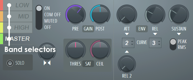
The input signal is split into three bands, LOW, MID and HIGH before being passed to the MASTER stage. The controls in the light grey panel change to reflect independent settings for the selected band.
NOTE: The LMH band-split filter type can be set as IIR or Linear-phase, see the General Options menu. Set by ear depending on the material. Normally IIR will be OK, but if the low-end seems to have smeared transients, try Linear-phase.
Target Band Settings
Selecting these tabs allows independent control of the 3 frequency bands and the Master controls. The cutoff frequencies for the bands can be adjusted using the LOW and HIGH frequency knobs, or by dragging on the BAND display mode.
- LOW (Red) - Low frequency band.
- MID (Orange) - Mid band.
- HIGH (Yellow) - High band.
- MASTER (Green) - Master controls.
Mode Settings
A series of controls surrounding the target-band selection controls:
- ON- Turns the selected band ON.
- COMP OFF- Turns the compression envelope off, leaving other aspects of the band active.
- MUTED- Mutes the selected band.
- OFF- Turns the selected band OFF.
- SOLO- Solos the selected band.
Stereo Enhancer
- Stereo Separation - The stereo separation control increases or reduces unique L/R channel stereo information in the signal. In the default position (middle), the stereo separation filter is disabled. To increase stereo separation turn to the left, to decrease the stereo separation, turn to the right. The enhancer works on the differences between the L and R channels and so will have no effect on a mono signal. Uses include narrowing the stereo information in the bass frequencies and add more separation to the high frequencies; a process applied to many master mixes.
Gain Section
These knobs control the input and output levels for each band-compressor.
- PRE (Purple) - Pre-compression gain. Useful for raising the level of a band into the active compression region.
- POST (Blue) - Post-compression (make-up) gain.
Saturator Section
The following controls will add saturation (valve/tape style 'overdriven' distortion) effects to the selected band. This is a subtle effect so don't expect the sort of sound you would get from a guitar distortion pedal.
- THRES (Level and Type) - There are two types of Saturation A (turn left) and B (turn right). Sets the threshold by the amount the knob is turned in either direction. Set the type by ear. NOTE: Adjusting type A saturation (left), while Maximus is processing audio, may cause clicking as a look-up table is re-calculated, this is normal.
- CEIL (Ceiling) - Soft saturation ceiling. Represents the maximum amplitude that the simulated analog device can carry. Lower ceilings create harsher saturation.
NOTES & TIPS: Saturation (pleasing to some) is a type of amplitude distortion, usually associated with Valve / Tube Amplifiers, tape or analog circuitry. Generally, as a waveform exceeds the maximum amplitude that an analog system can carry, its shape is rounded or bent. This bending is a mild distortion that progressively increases as the input approaches the maximum (0 dB).
We suggest setting any band you wish to saturate to a hard-limiting envelope and allow the input to peak a little over 0 dB, then blend in some 'Soft-clip' from the saturator. Superb results can come from a combination of these two.
Envelope Section
The envelope controls affect the dynamics of the envelope response.
- ATT (Attack time) - Adjusts how quickly the envelope responds to the start of the signal (in ms). NOTE: The MASTER attack time also sets the 'look-ahead' time for the Master channel and so affects the latency of Maximus. The purpose is to allow the compressor algorithm to see transients before they arrive, so they can be reacted to instantly. As it's impossible to look into the future, realtime processing is delayed so the incoming audio-stream can be previewed. This adds latency to the plugin. The ATT control for LOW, MID and HIGH does not affect look-ahead delay. These must stay in sync so look-ahead delay is set by a 'grouped' LMH delay control (see below). Since there are two look-ahead delay controls, the total look-ahead / latency for Maximus = MASTER ATT time + LMH Delay (see below).
- CURVE (Attack & Release 2 curves) - Select from curve 1 (steep slope) to 8 (low slope). This control sets both the Attack and Release 2 curves. These interact strongly with REL and REL2 release times, so use in conjunction to achieve the 'sound' you are looking for.
- REL - Release time (in ms). REL has an accelerating curve shape. See also REL 2 (below). To use either in isolation set the other to 0.
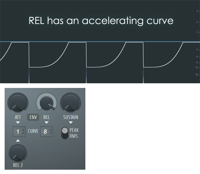
NOTE: In the example above the CURVE setting is to a low slope of 8, REL 2 is at 0 ms (no effect) and the release time is around 1700 ms to clearly demonstrate the release shape. At shorter release times and steeper curves settings, the shape will not be as visible on the display. REL and REL2 may be blended by setting both. The compression curve was triggered with an audio spike.
- REL2 - Release 2 time (in ms). REL2 has a decelerating curve shape. See also REL (above). To use either in isolation set the other to 0.
When used together they will interact to create blended release shapes. The overall release curve shape you are interested in will depend on the audio you are compressing.
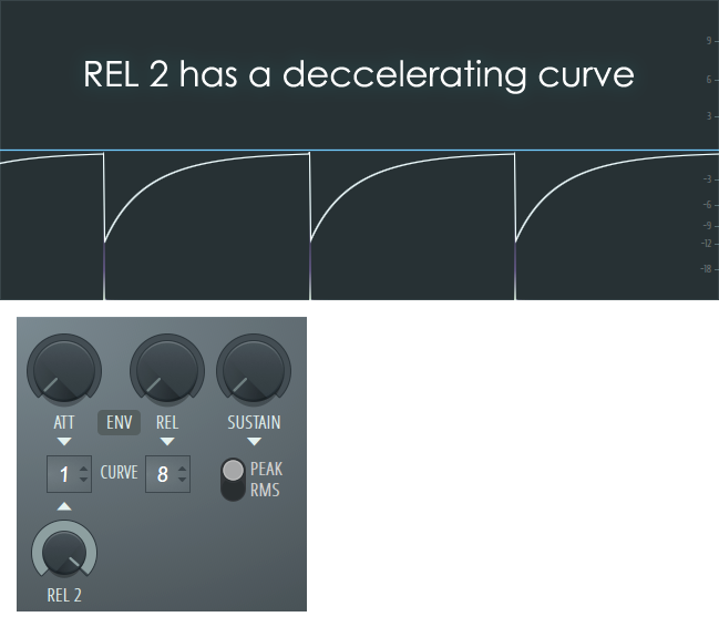
NOTE: In the example above the CURVE is set to a low slope of 8, REL is at 0 ms (no effect) and the release time is around 1700 ms to clearly demonstrate the release shape. At shorter release times and steeper curve settings the shape will not be as visible on the display. The compression curve was triggered with an audio spike.
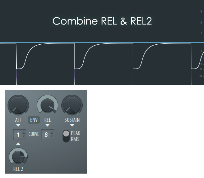
- Combining REL and REL2 - Combining both controls will allow you to create more complex release shapes. For example, a release that happens on the off-beat (1/2 beat) is often favored to create a 'syncopated' ducking or sidechain effect. The compression curve below was triggered with an audio spike.
- SUSTAIN - Specifically, this sets the duration over which the input is averaged (RMS), from 0 to 1000 ms. The effect is to control compressor sustain time and prevents the compression envelope from releasing too early.
- PEAK - Peak detection, best suited for Limiting. This mode tracks the instantaneous peak level of the input signal and will give the fastest detection of transients and therefore the quickest compression response. Peak detection is most appropriate when the compressor is used with a high compression ratio, to prevent clipping.
- RMS - RMS (or average input) detection. RMS mode allows transients to pass but the compressor will still respond to longer-duration sounds. It's best suited for compression of instruments or vocals. RMS is favored for these duties as it is less likely to affect the transients in the original material and result in a smoother, less aggressive and more natural sounding compression. NOTE: Don't rely on RMS for any final level control, remember those transients are passing uncompressed.
PEAK vs RMS NOTE: For the master band, a limiter (PEAK mode) is normally used. For the other bands, PEAK or RMS is used depending on the desired results. Most analog compressors work in RMS mode, however peak generally gives better results with complete mixes.
Band Frequency Controls
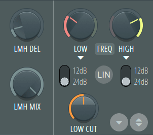
Low, Medium, High Look ahead Delay
- LMH DEL (Low, Medium, High Delay) - Look-ahead delay, used for the LMH band compressors. The LMH bands are grouped as they must stay in sync. The purpose of this delay is to allow the compressor algorithm to see transients before they arrive, so they can be reacted to instantly. As it's impossible to look into the future, realtime processing is delayed so the incoming audio-stream can be previewed. This adds latency to the plugin. As the LMH bands must stay in sync, they require the same delay, so this is a group delay control for the LOW, MID and HIGH bands. NOTE: The LMH delay + MASTER compressor ATT control delay (see above) add latency to Maximus' output, so delay compensation will be required if Maximus is used on anything other than the Master Mixer track, when LMH is set. Maximus, delay will display in the Hint Panel when you hover your mouse pointer over Maximus FX slot. Adjusting the LMH delay while Maximus is processing audio may cause some clicking as the delay is reset, this is normal.
- LMH MIX (Low, Medium, High Mix) - The mix between plugin input & LOW, MEDIUM, HIGH output, i.e. Turn fully left (counter-clockwise) to pass dry input to the MASTER (0% LMH) and fully right to pass 100% LMH to the MASTER. Used in 'NY Compression' techniques.
NOTES: The LMH delay parameter determines how far ahead Maximus looks into the signal and is useful for allowing fast transients through then limiting. This parameter relates to detected input signal levels for the compression envelopes. As a real-time level monitoring system can't know what level a signal was at AFTER it has happened. This means the compression envelope will react a few samples later. By seeing a few ms into the future compression/limiting can be timed perfectly to be at the right level for any given moment. As looking into the future is impossible, we move the audio stream into the past (delay it), so the algorithm is now looking at the present while the audio it needs to process in the past (buffer). This has consequences...
When a LMH delay is set, Maximus will introduce a delay to the output equal to the look-ahead value so that inputs can be pre-analyzed. Using long look-ahead times on mixer tracks, other than the master, will require Plugin Delay Compensation (PDC). For the master band, the delay is the attack length. The total delay of Maximus is equal to the LMH delay + Master attack. For effective LMH channel limiting, the LMH delay must be equal to the longest attack of those channels. For compression, other settings are usable since some transients can be allowed to pass uncompressed.
Frequency Control Section
These controls set the Low-Medium and Medium-High band cut-offs.
- LOW (Low Frequency Cutoff) - Sets the Low band frequency cutoff. You can also select the BANDS view and Left-click and drag the level and cutoff frequency.
- Low Band Slope - Switches between 12dB and 24dB per octave cutoff slopes. A higher value maintains greater separation between the boundary frequencies.
- LIN - When selected, Low and High filters run in Linear Phase mode. In this mode the filters do not rotate the phase of the underlying frequencies, but the process needs to apply latency. Normally automatic plugin delay compensation in the mixer will align the audio output. Linear Phase mode is based on advanced Fast Fourier Transform (FFT) filters.
- HIGH - High Frequency Cutoff) - Sets the High band frequency cutoff. You can also select the BANDS view and Left-click and drag the level and cutoff frequency.
- High Band Slope - Switches between 12dB and 24dB per octave cutoff slopes. A higher value maintains greater separation between the boundary frequencies.
- LOW CUT - A High-Pass filter on the input of the plugin. The default value is set to filter frequencies below 20 Hz. Improves headroom without affecting the quality and depth of the audible bass.
Comparison Bank

In the bottom right corner you will find:
- Store in spare state (Down arrow symbol) - Saves the current state to the comparison bank. Lock spare state, under the General options, allows this state to be protected from overwriting.
- Flip with spare state (A/B compare) - Selecting this control will allow you to make A/B comparisons between the stored and current settings. Useful for hearing the effect of a tweak more clearly.
Arthur: I wonder what will happen if I press this button?
Ford: What happened?
Arthur: A sign lit up saying 'Please do not press this button again'.
The Hitch Hiker's Guide to the Galaxy (1981)